![]()
01/27/2016 By Alex Tongue, Optical Sensing R&D and Application Engineer, Sensuron
New technologies can often be intimidating to implement for a number of reasons, but one of the most common hurdles is a lack of understanding how the technology works or how it can be applied. Fiber optic sensing (FOS) is such a technology, but it’s not that hard to understand the basics. A look inside FOS can help open your imagination to the possibilities.
Although FOS technologies have existed for a couple of decades, advancements in the past five years have propelled the technology into new markets by expanding addressable applications. Historically, FOS technologies have been developed for specific solutions in niche markets. Today, there are a handful of FOS technologies that are being developed that can be deployed in a myriad of applications ranging from monitoring how composite materials cure to determining the deflection of an aircraft wing in real time.
Specifically, FOS systems that use fiber Bragg gratings (FBGs) have undergone tremendous advancements in the past few years. Two notable innovations are the transition from point sensing solutions to spatially continuous solutions as well as the addition of real-time multi-parameter sensing functionality. Here, we’ll take a look at the operating principles behind optical frequency domain reflectometry (OFDR), one of the types of FBG-based technologies that make distributed multi-sensing possible.
The core of most FOS technologies, whether they use FBGs or not, is interferometry. Simply put, interferometry is a family of techniques in which waves are superimposed to extract information about the waves. In FBG-based systems, light reflected back to the interrogator (light source) gets superimposed with other reflected signals, and the resulting interference signals get translated into strain or temperature data. To understand the operating principles behind OFDR, a better understanding of optical fiber and FBGs is necessary.
Fiber Optic Cables and FBG Manufacturing
Fiber optic cables are composed of an outermost protective coating, and then two layers of glass. The outer layer of glass is referred to as the cladding, and the very small inner portion is called the core. The core is where the light travels and where the FBGs are inscribed. Fiber is typically produced on a draw tower, which is a standard fiber manufacturing installation that heat up glass tubes (preforms) and draws them out, creating the thin, multi-layer optical fiber.
During the manufacturing process, the core is made to be reactive to UV radiation so that a UV laser can inscribe the gratings. There are several techniques to execute this process of writing gratings. One manufacturing process inscribes the FBGs on a completed fiber. As a result, inscribing the gratings requires the fiber coating be stripped, the gratings written, and the fiber recoated. This process leads to reduced mechanical strength and can limit how the fiber is used in the field.
A more cost-effective method inscribes the gratings during initial fiber creation. A UV laser installed on the draw tower writes the gratings as the fiber is being drawn. The fiber with gratings is then coated and spooled. This process allows for separate or continuous gratings to be written and produces fiber with much higher mechanical strength.
Fiber Bragg Gratings—The Sensing Element
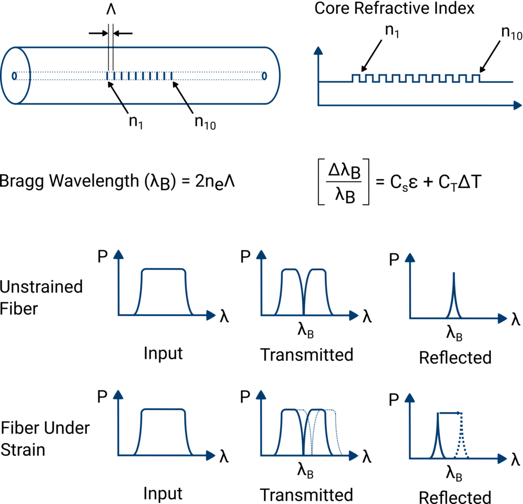
The fiber Bragg grating (FBG) forms the sensing element. FBGs are essentially microscopic, wavelength-selective mirrors, meaning they reflect a single, specific wavelength and transmit the rest of the optical signal that the interrogator generated. One way to think about this is with white light. White light consists of the entire color spectrum, or in other words, many different wavelengths. If white light was sent down a fiber incorporating a FBG, one would see a single color reflected, while everything else is transmitted.
To use the FBG together with OFDR, gratings are written continuously throughout the fiber. This means that reflections are being sent back to the interrogator from every point along a fiber’s length. The reflected wavelength at each location is referred to as the Bragg wavelength. When a fiber (hence, the grating) is stretched, compressed, or undergoes thermal expansion and contraction, the Bragg, or reflected wavelength, changes.
The interrogator then uses a demodulation technique to observe the change in wavelength and translate this into strain and temperature measurements. The relationship between mechanical strain and the Bragg wavelength is described in the figure below.
The technique used to interpret the superimposed wave created by the optical signals the FBGs have reflected largely determines a FOS system’s capabilities. Two of the most prevalent interpretation techniques are wavelength division multiplexing (WDM) and, as stated before, OFDR.
The biggest difference to note between the two techniques is that OFDR allows for fully distributed sensing while WDM offers tens of discrete sensors per fiber.
The demodulation technique being used has a significant impact on the performance that is possible with a FOS system. The demodulation technique largely determines system’s refresh rate, sensing length, number of sensors, spatial resolution, and the interplay these parameters. Certainly, there are other variables that impact the performance of a FOS system, but understanding the capabilities and limitations of demodulation techniques is essential when evaluating a FOS system for an application.
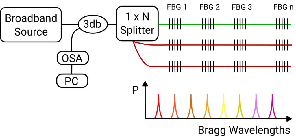
Wavelength Division Multiplexing (WDM)
For WDM systems, each grating must be written at a different Bragg wavelength, which means only tens of FBGs can be multiplexed on a single channel. Most WDM systems in the market have twenty to thirty FBGs on each channel. While WDM systems typically have more than one channel, they can generally only interrogate one channel at a time.
The number of sensors per channel is limited because the reflected wavelengths cannot be written close to each other. If the Bragg wavelengths are too similar, a grating under strain could shift to reflect the same wavelength as another grating, making the data useless. While WDM fiber sensors can have long lead lengths, only points of information can be obtained. If an event occurs between sensors, the user will miss critical data.
WDM systems can have high refresh rates, but each additional sensor added to a channel will significantly reduce its capabilities. Another limiting factor for WDM systems is that the user must specify exactly where the gratings need to be written on the sensing fiber. This means that each fiber must be customized for each project, a cumbersome process. The process of identifying where the gratings need to be inscribed, as well as lead times for custom fibers, can be lengthy.
Applications well suited for using WDM systems are those that only require a handful of sensing points but sense at very high speeds. For example, WDM systems can be used to measure strain on crash test dummies during the moments of impact or used to monitor detonation velocity in an explosion.
Optical Frequency Domain Reflectometry (OFDR)
The other demodulation technique, OFDR or swept laser interferometry, can be used to determine both what and where events are occurring all along an optical fiber. There are two separate things that are being interrogated with OFDR: what wavelength of light is being reflected at any given point along a fiber’s length, and at what distance along the fiber that particular wavelength is being reflected from.
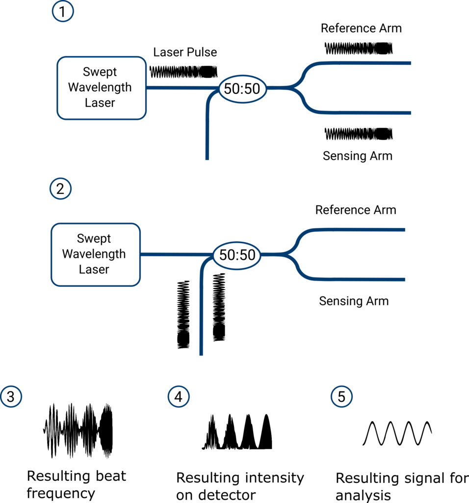
OFDR interrogation starts with a narrow linewidth, continuously swept light source. By narrow linewidth we mean that the light source emits roughly a single wavelength at any given instant in time. Continuously swept means that the light source sweeps its output across a given wavelength range. One full sweep across the wavelength range corresponds to one full acquisition of the FBG sensor array along the length of the fiber.
When the interrogation signal launches, the light travels down the fiber and at every point along its length, a single wavelength within the sweeping range gets reflected. The strain or temperature at each point along the fiber, because they have altered the spacing of the grating lines, determines the wavelength that gets reflected at that point. Therefore, where reflections are seen during the sweep of the laser the wavelength being reflected reveals details about the strain or temperature.
One full sweep of the laser yields reflected wavelengths coming from each of the gratings along the entire fiber – so interferometry comes into play to separate the multitude of signals. On its way back to the system, all of the reflected light is allowed to interfere with a reference signal and the result goes to an optical detector. The interference between the reference optical wave and each of the reflected waves results in frequency modulated signal information from the sensor.
Reflections coming from early parts of the fiber (nearer the interrogator) modulate, or beat, at low frequencies. Reflections from far down the fiber modulate at high frequencies. Spectral analysis then reveals which reflections are returning from what point along the fiber.
Because the FBG sensing is occurring in a spatially continuous manner down the fiber’s length, the OFDR system enables the acquisition of fully distributed strain and temperature profiles along the fiber. This information can then be processed to reveal further detail. Other measurements that can be derived from these profiles include deflection, 3D shape, liquid level, pressure, and magnetic fields.
Because the gratings have been continuously written, OFDR technology offers significantly higher spatial resolution and exponentially more sensors than other sensing technologies in the market. Such spatially continuous information provides a number of advantages to engineers across multiple industries. For example, distributed data from OFDR sensing systems equips engineers with the data necessary to confidently validate their thermal, vibration, or strain models of a design and avoid costly failures after production has begun.
Sensuron’s OFDR FOS systems, for instance, have been used in a number of applications including locating and tracking crack propagation in fatigued wind energy blades, monitoring folding and wrinkling of composite materials during manufacturing, and even determining the degree of unforeseen plastic deformation in critical load-bearing aircraft components.
Another benefit of OFDR FOS systems is that they can have multi-sensing capabilities, or the ability to monitor multiple parameters on different channels simultaneously. For example, the technology has been used to simultaneously monitor strain, deflection, temperature, and load of an aircraft wing in real time during flight testing.
The multi-sensing abilities and distributed data breakthrough that FOS sensing has made in the last several years will empower engineers to solve the design problems they face today and innovate beyond the problems of tomorrow. Now that you understand how it works, there is no longer a need to be intimidated by the technology.